Infrared is an incredibly underrated communication medium, used almost exclusively in television remotes these days. Despite its poor range (<10m) it is incredibly useful for short range communication (particularly in robots), and its extremely low component cost, energy usage, and complexity make it a candidate for inclusion in any makers arsenal.
Knowing this, and wanting to develop my circuit board design skills, I resolved to create a circuit that could continuously send out a continuous IR signal, a beacon if you will. This has a number of applications:
- It can be used as a beacon for robots (or appropriately-tooled humans!) to geolocate or otherwise orient themselves.
- It can be used to transmit the state of a mechanism (such as a traffic light) for a robot to understand (ie: stop before you get run over, or the door is locked)
- It can be used for short range communication between a fixed and a mobile peripheral.
Board Layout Board Schematic
I settled on using a PIC microprocessor (a 12F683) as the core of the beacon, due to its extremely low power consumption, low cost and simple pinout. I also used a BC548 general purpose NPN transistor to drive the IR emitter (which was a high power IR LED I picked up from element14), as the IR needed to be driven with several hundred mA when the PIC can only provide 20mA.
I did all my calcuations for max current at 3.3V, and hence choose current-limiting resistors at that value. As such, the board can run at 3-3.5V no problem, though anything over 4V you run the risk of killing the indicator LED or reducing the life of the IR LED. The PIC itself will burn out at 5.5V.
After waiting 4 weeks for the boards to arrive fabricated from china, I put together 5 of them. They work a charm, with ranges of up to 10m or so, and run for about a week on 2 AA batteries. All in all, I'm really happy with this project.
PIC Code PCB Ordering link

Now to put it to actual use ...
When it first came out, the ESP8266 chip was a game changer. For $5, any electronics hobbyist could get a functional WiFi chip to integrate into their next internet-of-things project. There were only a few problems. Well, a fair few problems.
All the documentation is in Chinese. Translated by the community! Yay!- All logic is 3.3V, whilst the arduino and other popular platforms use 5V.
- Peak current consumption at 240mA, far greater than the capacity of most built-in regulators on an arduino or similar board.
- CH_PD pin needs to be pulled high for the device to function (It took me forever to work this out - most of the tutorials I read seemed to omit this detail)
- Firmware bugs - occasionally the chip stops responding completely and needs a power cycle.
So I set out to build a circuit that would solve some of these issues - particularly the ones that plagued me. I built a circuit that would translate the voltage level on the receive side, would regulate the current, and provide a jumper for the CH_PD pin.
After a fair few hours fiddling with KiCad, I think I've done it.
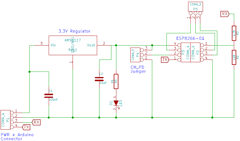
The circuit uses only cheap components. A AMS1117 (you can get a pack of 10 for $1 on ebay) is used as the regulator, and it supports up to 1A of current so no worries there. The resistors used in the voltage divider are 0805 SMDs, so no worries there. The LED is once again an 0805 and can be omitted if you don't like color.
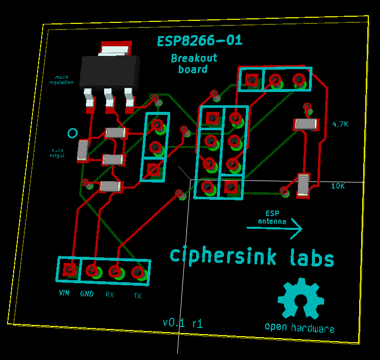
I eventually figured out how to add text to the silkscreen, at which point I promptly went overboard and labelled everything relevant, even the direction the ESP8266-01 should be inserted.
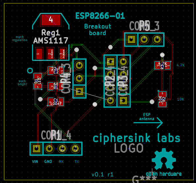
Yay! Now to wait a few weeks for the boards to ship from DirtyPCBs so I can assemble and test them. Very suspense, especially since this is only the second ever PCB I have designed (hopefully it works).
If your interested, you can order your own set at dirtyPCBs.
Design files are available here.